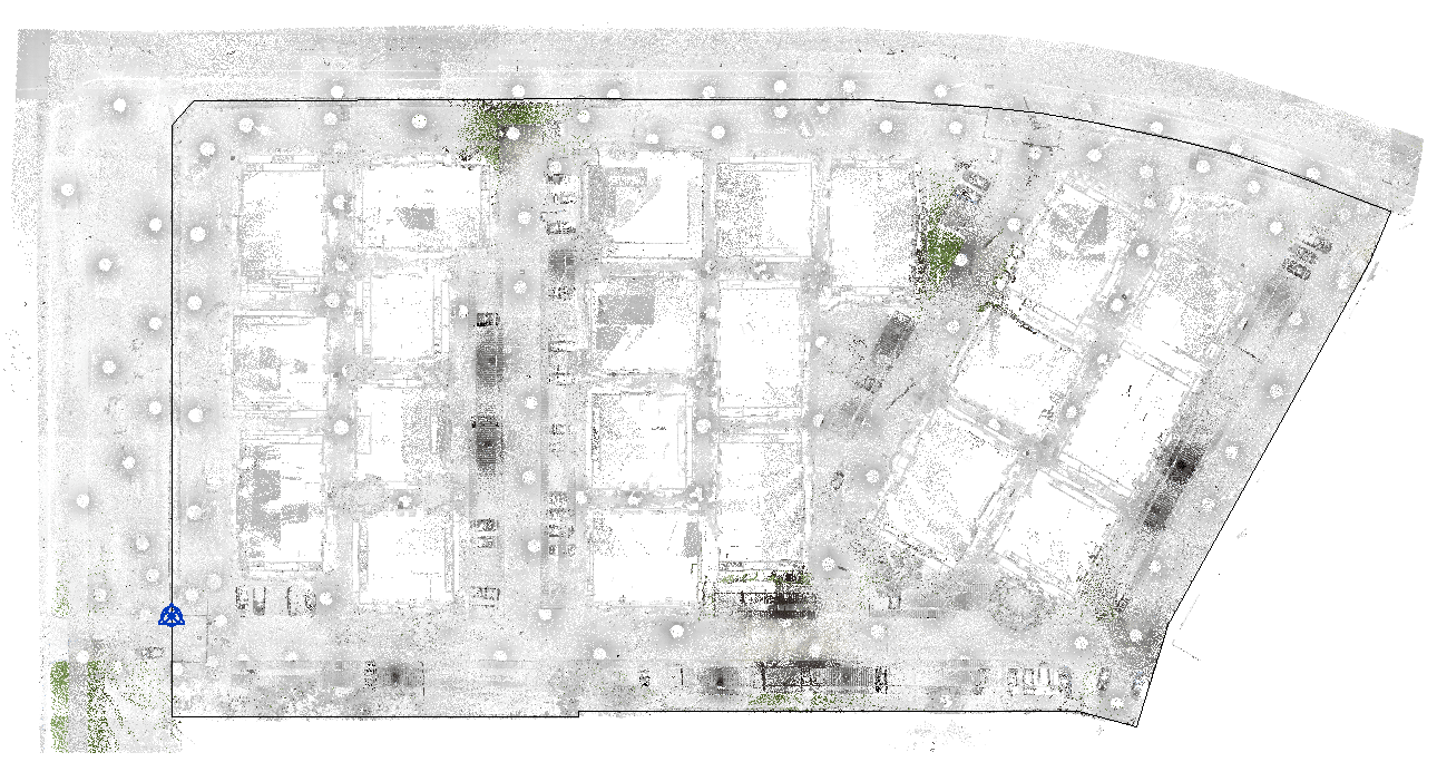
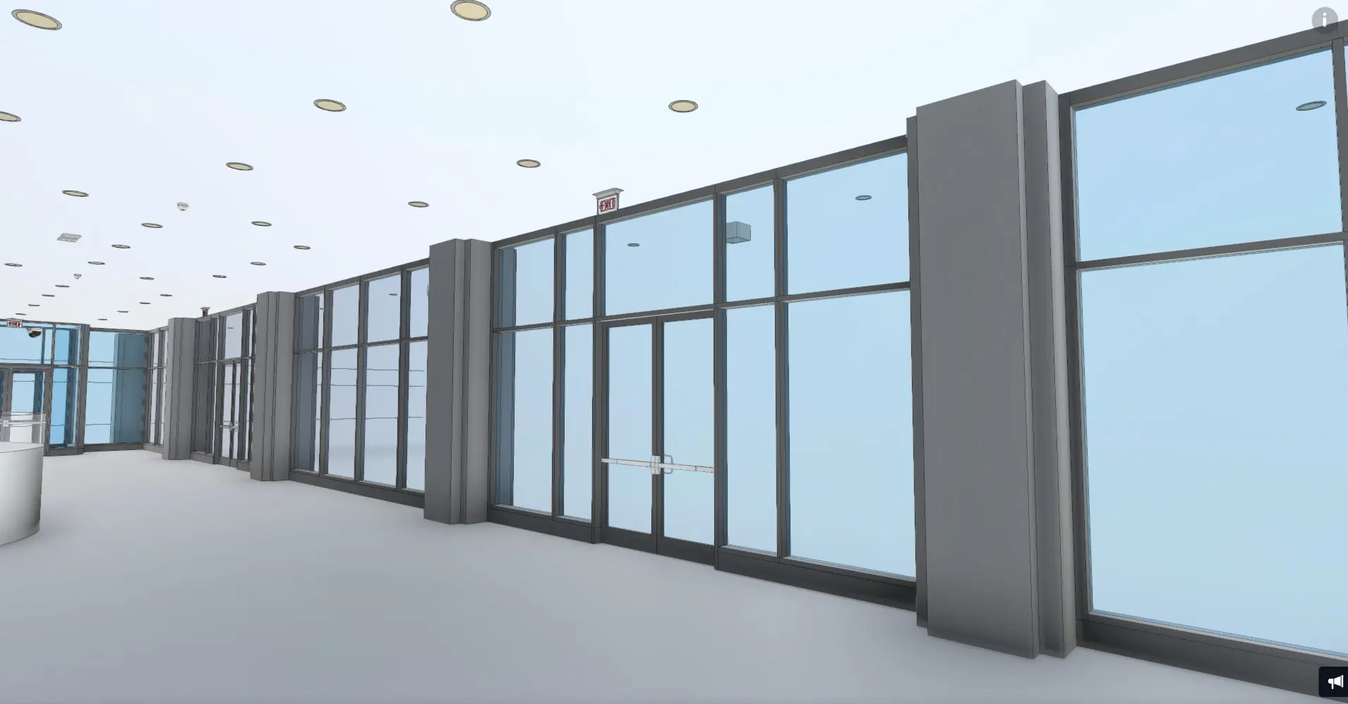
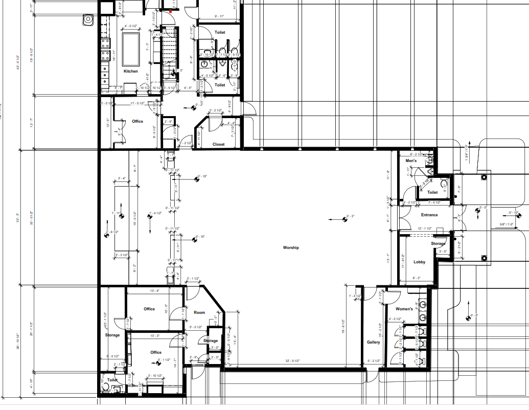
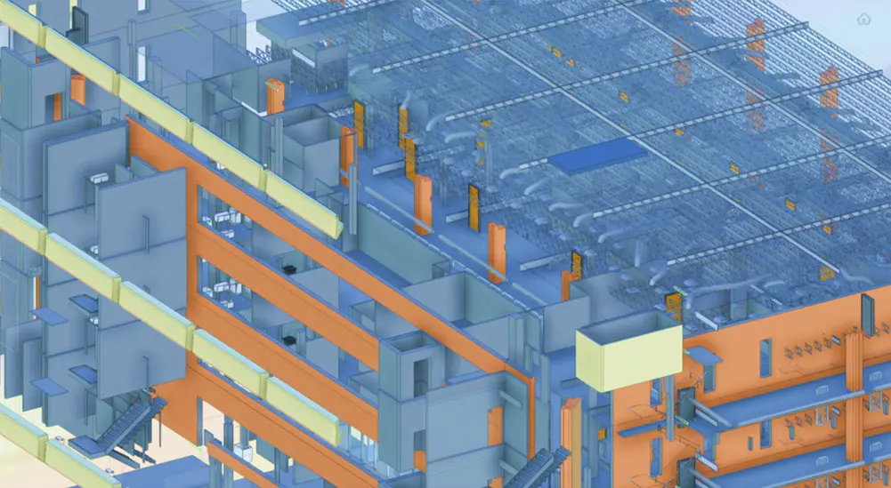
The process for importing point cloud into Revit is simple and user friendly, however some work must take place upfront to ensure that we only import the data we need for our project. A Point cloud is a set of data points in some coordinate system defined by X, Y and Z values that represent the surface of an object. Point Cloud is the data type resulting from a 3D laser scanner used to measure dimensions of space in 3D. Point cloud is practical, low cost, and accurate way of documenting existing dimensions. In the AEC industry, it is mainly used in building renovations, construction verification and as-built analysis.
3D laser scanners typically scan the surrounding environment in a spherical way (360° Horizontal x 270° Vertical) which means, they cover about 90% of a sphere. Let’s take for example a scan that was taken outside a building, you will see the trees, the parking lot, utilities, etc. All of which may not be needed for your Revit modeling. Before importing this point cloud into Revit, you will need to delete all point cloud scenes that you don’t need otherwise, the size could be massive and will hinder the computing power of your pc causing it crash. So, as a rule of thumb, always remove point cloud that is not relevant to your project as a first step. This can be done using AutoDesk Recap. Another useful tool for manipulating point clouds like changing the point size, scale and geo-referencing is CloudCompare, which is a free and open source software. Other issues you might face with point cloud files include density, lack of color, scale and units. Most of these issues can be overcome using Recap and CloudCompare
Once the point cloud is ready for your use, you must save it in Autodesk Recap so that the format can be recognized by the latest versions of Autodesk Revit, that is, files with rcp or rcs extensions. The next step is to run the Point Cloud command on the Insert tab of Revit to import it.
Once the point cloud has been imported into Revit, it is possible to configure its visualization to help the modeling processes. This is achieved using the visualization command (VV) which gives you three options.
Option 1, assign a specific color to the cloud, option 2, assign colors according to the value of each point in the Z coordinate and option 3, assign color values according to the orientation of the normal vector, which is very useful for differentiating roof walls and other constructive elements.
To start modeling in Revit, it is necessary to locate the point cloud in the correct position within the file that coincides with the levels and the point of origin of the project. You can use section views and “Section Boxes” tools to accomplish that.


