Nationwide Service | Houston Headquarters

Industrial Scanning Guide

Industrial Laser Scanning Guide: Planning, Capture and Modeling

This guide explains how industrial laser scanning projects should be scoped, planned, captured, registered, quality checked, and converted into usable point clouds, CAD drawings, Revit models, and plant documentation. It also addresses site safety, access planning, survey control, operating constraints, deliverable definition, and client review.

Environment
Operating Industrial Facilities
Primary Capture
Terrestrial 3D Laser Scanning
Production
Point Cloud, CAD, Revit or Plant Models
Key Requirement
Clear Scope and QA/QC

Overview

Industrial Scanning Is a Production System, Not a Single Field Visit

Industrial facilities contain dense systems, restricted areas, active operations, elevated platforms, line-of-sight limitations, and safety requirements that directly affect the quality and completeness of a scan.

A reliable project requires more than collecting point clouds. The scope must connect field planning, safety, coordinate requirements, scan coverage, registration, quality control, model content, file formats, and acceptance criteria.

The methodology below is based on recurring elements found in Reality IMT’s historical industrial proposals, modernized and generalized so it can be used without exposing confidential client or pricing information.
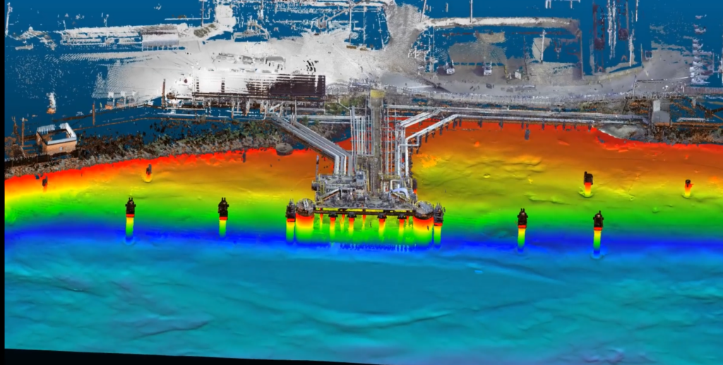
Industrial as-built survey,Bathemtric Survey in 3D using Multi-beam sonar and laser scanner

Article Details

Content Type
Primary Audience
Reading Time

Phase 1

Project Definition and Scope Boundaries

Before mobilization, the team should define the plant areas, levels, systems, accessible spaces, required coordinate framework, model content, intended use, and final file formats.

Industrial scopes should also state what is not included, such as concealed systems, underground utilities, insulation thickness assumptions, inaccessible equipment, or systems outside the agreed discipline.

Phase 2

Safety, Access, and Field Planning

Site Safety Requirements

Orientation, PPE, permits, escorts, hazardous areas, work windows, and emergency procedures.

Operating Constraints

Production schedules, shutdowns, hot work, restricted equipment, vibration, and moving machinery.

Access Planning

Elevated platforms, ladders, lifts, scaffold, confined spaces, roofs, and locked areas.

Control and Coordinates

Plant grid, survey control, local coordinates, model origin, elevation datum, and orientation.

Coverage Planning

Scanner positions, overlap, visibility, density, color or imagery needs, and blind areas.

Daily Data Management

Field backups, naming, logs, issue tracking, and transfer to processing.

Phase 3

Field Capture and Coverage Verification

The field team should collect sufficient overlap to register the scans and should review coverage before leaving each area. Dense piping, equipment, structure, and elevated systems may require multiple viewpoints.

Photographs, 360 imagery, field notes, control observations, and issue logs may supplement the point cloud when needed.

Phase 4

Registration, Cleanup, and Point-Cloud QA/QC

Registration

Align individual scan positions into the agreed coordinate framework using targets, cloud-to-cloud methods, survey control, or a combination.

Cleanup and Organization

Remove obvious transient noise where appropriate, segment areas, preserve raw data, and organize the project for production.

Coverage Review

Identify gaps, inaccessible areas, excessive occlusion, movement, or data that does not meet the intended use.

Quality Reporting

Document registration performance, coordinate checks, exceptions, and any known limitations that affect modeling or measurement.

Phase 5

Modeling and Drawing Production

The production scope should identify the required disciplines and level of representation. Architecture, structure, piping, equipment, and cable trays may require different modeling rules and tolerances.

The model should be developed against the point cloud and reviewed at defined milestones. Unknown specifications should not be invented; dimensions or classifications not visible in the scan should be identified as assumptions or omitted.

Deliverables

Common Industrial Project Outputs

Registered Point Clouds

E57, RCP/RCS, LAS, LGSx, or other agreed formats.

CAD or Revit Models

Existing-condition models developed to the specified discipline and detail.

Plant-Design Models

Project-specific modeling for piping, equipment, or plant workflows where agreed.

2D Drawings

Plans, elevations, sections, equipment layouts, or other extracted documentation.

Visual Review Files

360 imagery, viewers, markups, screenshots, or issue records.

QA/QC Documentation

Registration summaries, coordinate checks, exception logs, and delivery records.

Client Review

Review, Revisions, and Acceptance

Industrial modeling benefits from planned review milestones. The owner or engineer should verify naming, discipline priorities, equipment identification, plant standards, and intended design use.

The proposal should define review rounds, response time, change control, and how scope additions will be handled.

Intended Audiences

Who This Guide Is For

Plant Owners
EPCs
Mechanical and Process Engineers
GIS and Engineering Teams
Transportation Agencies

Need an Industrial Scanning Scope Built Around Your Deliverables?

Send us the facility area, operating constraints, coordinate requirements, systems to model, and required file formats.