
Nationwide Service | Houston Headquarters

Rail & Infrastructure

Rail Corridor Mapping Guide: LiDAR, Imagery and Survey Control

This technical guide explains how mobile LiDAR, 360 imagery, GNSS/INS positioning, survey control and engineering production workflows support rail corridor planning, track surveys, asset documentation and design. It also outlines common deliverables and the questions owners and consultants should resolve before issuing a rail mapping scope.

Environment
Rail Right-of-Way
Technologies
LiDAR, 360 Imagery, GNSS/INS
Typical Outputs
Plan/Profile, Track Charts, Asset Records
Primary Users
Engineering, Signals, Operations and Maintenance

Overview

A Rail Corridor Is More Than a Centerline

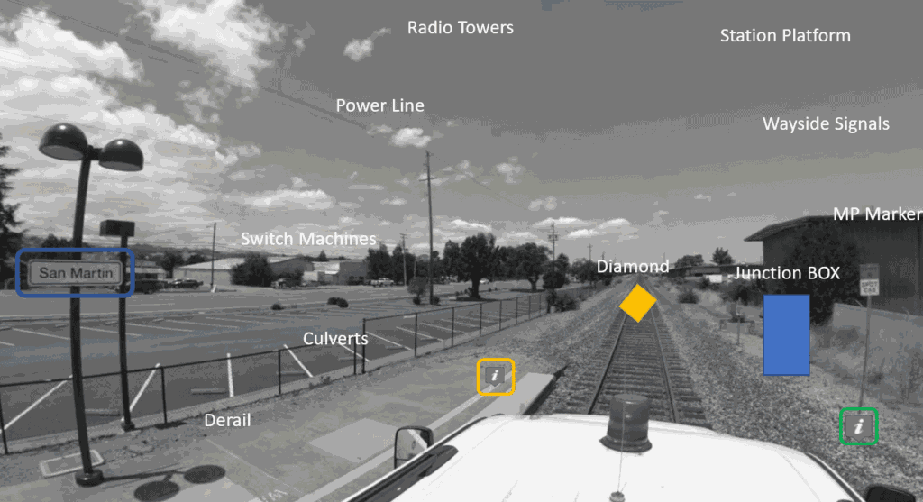
Rail documentation may need to represent track geometry, grades, curves, turnouts, crossings, structures, signals, drainage, platforms, visible utilities, access points, and surrounding right-of-way conditions.

No single sensor or deliverable is appropriate for every rail project. A visual mapping assignment for planning and asset review differs from a survey-controlled LiDAR scope intended to support plan-and-profile drawings or engineering design.

The correct approach begins by defining the intended decisions, required accuracy, access limitations, corridor length, and final deliverables.
Railroad Asset Mapping LiDAR and Surface Imaging

Article Details

Content Type
Primary Audience
Reading Time

Scope Definition

Start with the Required Outcome

A corridor used for conceptual fiber-route planning may only need georeferenced imagery and visible asset tags. A track-chart or plan-and-profile project may require survey control, mobile LiDAR, precise positioning, feature extraction, and CAD production.

Visual Corridor Mapping

Continuous 360 imagery for remote review, access planning, and visible asset documentation.

LiDAR As-Built Survey

Three-dimensional geometry for engineering extraction and measured corridor documentation.

Asset Inventory

Location-aware records of signals, crossings, structures, platforms, and other visible features.

Change and Condition Review

Repeat visual records that support comparison, maintenance, and condition discussions.

Technology Stack

Core Rail Mapping Components

Rail mapping systems typically combine several technologies rather than relying on one sensor.

Mobile LiDAR

Captures three-dimensional geometry around the corridor and visible assets.

Panoramic and Forward Imagery

Provides visual context for engineering, inspection, bidding, and coordination.

GNSS and Inertial Navigation

Establishes position and orientation during continuous movement.

Survey Control

Connects the mobile dataset to project coordinates and accuracy requirements.

Processing Software

Combines trajectory, imagery, LiDAR, and control into coordinated outputs.

Web or GIS Review

Makes imagery and asset information accessible to distributed stakeholders.

Engineering Applications

Common Rail Deliverables and Features

Depending on the scope, rail mapping can support plan-and-profile drawings, track charts, geometry review, visible asset inventories, and corridor documentation.

Track Geometry

Centerline, curves, grades, super-elevation, and related engineering features.

Turnouts and Crossings

Switches, diamonds, grade crossings, pedestrian crossings, and warning systems.

Signals and Communications

Bungalows, cases, boxes, control points, signal types, and visible communication assets.

Structures and Drainage

Bridges, culverts, platforms, ditches, ballast, and adjacent structures.

Clearance Context

Visible obstructions, overhead features, vegetation, and surrounding right-of-way conditions.

Plan and Profile

CAD documentation derived from survey-controlled corridor data.

Workflow

Typical Rail Mapping Workflow

1. Access, Safety, and Control Planning

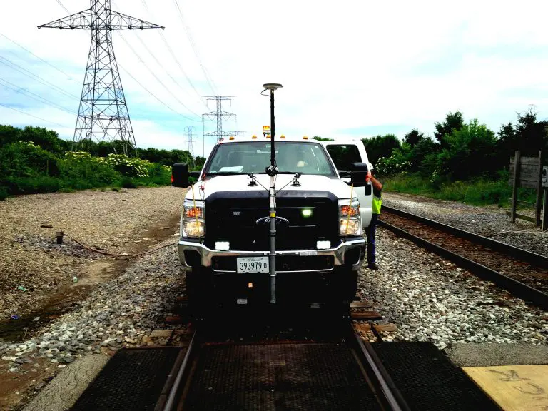
Coordinate railroad access, safety requirements, qualified personnel, equipment mounting, control, and operating windows.

2. System Calibration and Field Capture

Verify the imaging, LiDAR, positioning, and storage systems before collecting production data.

3. Trajectory and Sensor Processing

Post-process GNSS/INS data, align sensors, register LiDAR, and organize imagery.

4. Feature Extraction and Production

Extract required geometry and visible assets into CAD, GIS, databases, or web-viewer records.

5. QA/QC and Delivery

Review control, coverage, feature coding, file organization, and final outputs against the agreed scope.

Procurement

Questions to Resolve Before Issuing a Rail Mapping Scope

What is the intended use?

Visual planning, survey, engineering design, asset inventory, bidding, or condition review.

What accuracy is required?

The requirement should be tied to the deliverable rather than a generic technology claim.

Which assets must be extracted?

List required rail, signal, structure, crossing, drainage, and utility features.

How will the corridor be accessed?

High-rail, train, maintenance vehicle, walking crews, or a mixed approach.

What outputs are required?

Point clouds, imagery, CAD, GIS, plan/profile, track charts, asset tables, or hosted viewers.

How will data be maintained?

Define ownership, hosting, retention, updates, and future access.

Intended Audiences

Who This Guide Is For

Rail Engineers
Surveyors
Signals
Operations and Maintenance
rail right of way mapping with LIDAR and 360 cameras

22 Apr 2020

40-Mile Commuter-Rail Corridor Documented with LiDAR and 360 Imagery

Reality IMT supported a commuter-rail documentation program covering approximately 40 miles of active right-of-way. The…

CONTINUE READING

Need Similar Documentation?

Send us the location, approximate size, available information, and required deliverables.